Finding the right chemistry
A multiscale digital model offers new insights for tantalum coating deposition.

Industrial chambers are intricate machines. Gas enters through inlet pipes, products leave through an exhaust pipe, heat conducts through walls and components, and chemical reactions take place across surfaces with complex shapes. Change the position of an inlet by a small amount, adjust a flow rate or introduce a baffle, and the effect can be felt throughout the entire process.
This makes chamber optimisation difficult, time consuming and expensive. In a multi-million-pound bespoke facility, trial and error is not an attractive design strategy. Each experimental run takes time and consumes materials, while measurements inside an operating chamber can be challenging or impossible to make. More importantly, a change that improves quality in one region may create an unwanted effect somewhere else.
AWE faced exactly this challenge in a large-scale chamber used for chemical vapour deposition (CVD) of tantalum metal onto substrates with complex geometries. Our aim was to obtain the best possible performance from a state-of-the-art industrial system with consistent deposition, reproducible products and efficient use of both equipment and starting materials.
To do that, we needed to understand events occurring across a range of scales, from the breaking of individual chemical bonds to the movement of gases around an entire chamber. The answer to this was to use a multiscale modelling approach.
The team combined quantum chemistry, kinetic Monte Carlo (KMC) simulation, computational fluid dynamics and carefully designed validation experiments.
Inside the chamber
The process of CVD uses gaseous starting materials to produce a solid coating on a surface. Although the basic idea sounds straightforward, the quality of the final deposit depends on a tightly connected collection of physical and chemical processes.
In our system, tantalum metal chips are converted into gaseous tantalum pentachloride (TaCl5) in an external chlorinator. The TaCl5 is then introduced into the deposition chamber, where hydrogen gas enters separately. At the substrate surface, the tantalum-containing precursor is reduced, leaving tantalum metal behind while hydrogen chloride (HCl) is released as the gaseous by-product.
The overall chemistry is represented simply as:
TaCl5 (g) + 2.5H2 (g) → Ta (s) + 5HCl (g)
However, the equation hides the process’s technical nuances. The rate at which tantalum is deposited depends on local temperature, the partial pressures of TaCl5 and hydrogen, the availability of reactive surface sites and the ease with which the individual reaction steps can occur. Those conditions are not the same everywhere.
Gas velocities vary around the chamber, temperature gradients develop, reactants are consumed and products accumulate. A complex substrate can also disturb the flow, creating regions with very different local chemical environments.
This is where local detail becomes essential. Knowing the total material flow into the chamber is not enough. We need to know what conditions exist at each part of the substrate and how those conditions change as deposition proceeds.
A conventional, single-scale model reaches its limits at this point. Computational fluid dynamics (CFD) can predict where gases travel, but it cannot determine the reaction mechanism from first principles. Atomistic calculations can describe reactions in detail, but cannot simulate an industrial chamber atom-by-atom. No single modelling technique spans the whole problem. So instead, we built a chain of models with each scale feeding information to the next.
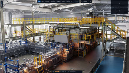
The starting point for this work was a high-fidelity digital representation of the chamber. Starting from engineering drawings, our team reconstructed the equipment geometry on a computer, reproducing the relevant internal features to millimetre-scale accuracy. This includes the main chamber volume and the elements that control how gases move through it, such as inlets, outlets, substrates, supports, baffles and other internal structures.
Within this digital twin, the CFD divides the chamber volume into a large number of small computational cells. Within each cell, equations describing fluid flow, heat transfer and species transport are solved numerically. The calculation shows how gases entering through an inlet spread through the chamber, how they accelerate or slow down, where they mix, and where regions of recirculation or stagnation may develop.
From this, we can predict quantities that would be extremely difficult to measure throughout a working chamber. These include local gas velocities, temperature gradients and the partial pressures of TaCl5, hydrogen and HCl. Direct measurement is impractical because the chamber interior is hot and chemically aggressive. The corrosive species present, particularly HCl, rapidly destroy any sensor placed inside, so these quantities simply cannot be probed experimentally.
The model can be visualised as a series of 3D maps (below). Rather than seeing the chamber as a single vessel operating at one temperature and pressure, we see a dynamic chemical landscape. Every location has its own combination of flow, temperature and composition, and therefore its own potential deposition rate. Nevertheless, identifying the local conditions solves only half the problem. To calculate how quickly tantalum forms, we also need to know how the chemistry responds to those conditions.
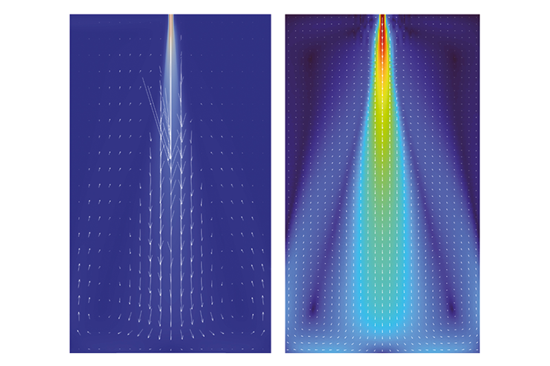
Velocity vectors from the computational fluid dynamics model of the chamber, showing tantalum pentachloride (TaCl5) injected as a focused central jet from the top inlet while hydrogen enters through the side inlets. The left panel shows velocity vectors, illustrating the flow field and directionality of the two reactant streams. The right panel shows a velocity magnitude heat map, highlighting where the jet is fastest, and how it decelerates and spreads as it mixes and transports towards the deposition zone
© Crown owned copyright 2026/AWEWho’s got the chemistry?
The overall reaction suggests that TaCl5 and hydrogen meet and form tantalum and HCl. Questions remain about where that transformation occurs and through what sequence of steps. Computational chemistry investigates these questions at the molecular level.
The first possibility considered was a gas-phase reaction, in which TaCl5 and hydrogen react with one another while still moving through the chamber. Calculations using density functional theory (DFT) of the relevant activation barriers and thermodynamics indicate that only the first reduction step – the initial interaction of TaCl5 with H2 to form TaCl4H and HCl – is feasible under the conditions of interest (see image below).
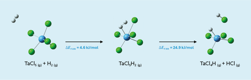
The density functional theory-calculated reaction pathway for the initial gas-phase interaction between tantalum pentachloride (TaCl5) and hydrogen (H2). The reaction on the right shows the stepwise formation of TaCl5H2 followed by hydrochloric acid elimination to form TaCl4H and HCl. Tantalum is depicted as a blue sphere, chlorine as green spheres and hydrogen as white spheres
© Crown owned copyright 2026/AWE
Every subsequent gas-phase step, in which the partially reduced species shed further chlorines, carries an activation barrier that is too high to overcome on the timescales relevant to the process. In other words, the gas-phase route can begin, but it cannot run to completion. The TaCl5 is not reduced all the way to tantalum metal, so the reaction must be completed elsewhere.
Having established that complete reduction does not occur in the gas phase, the next step was to investigate how partially reduced tantalum chloride species behave at the surface. TaCl4 was used as a representative precursor for the surface reaction model, allowing the subsequent reduction and deposition chemistry to be explored using KMC simulations.
At the substrate surface, a more accessible reaction pathway becomes available. TaCl4 and hydrogen can adsorb onto the substrate, bringing them into contact with a chemically active environment. Once adsorbed, the precursor can undergo a sequence of reactions in which tantalum-chlorine bonds are broken and the chlorine containing fragments combine with hydrogen atoms. HCl gas is formed and desorbs from the surface, while tantalum remains behind as a solid deposit.
The substrate therefore plays an active role in enabling the chemistry. The process is an example of surface catalysis, whereby reaction pathways open up that are much more accessible than the equivalent reaction in the gas phase.
The DFT provides the energetics of the individual steps, giving the strength of adsorption, the relative stability of intermediates and the activation barriers separating one state from another. This creates a molecular-scale description of the deposition mechanism.
However, industrial coatings emerge from an enormous number of adsorption, dissociation, recombination and desorption events occurring across the surface. As such, the next challenge is to scale from individual reaction steps to a measurable deposition rate.
Capturing all the dimensions
For this, KMC simulation is used. This is a statistical modelling method that follows the evolution of a system through a sequence of possible microscopic events. At any point, a molecule might adsorb, a bond might break, an atom might move, or HCl might leave the surface. Each event is assigned a rate based on our DFT calculations and the local conditions.
By focusing on the chemically important events and working out which is likely to occur next, the simulation sidesteps the need to resolve every atomic vibration. Repeating this process many times builds up a picture of how the surface changes over experimentally meaningful periods. This gives us predicted deposition rates as functions of temperature and reactant partial pressures, which is essential for chamber modelling.
We can run the kinetic model over a range of conditions relevant to the chamber, asking a series of ‘what if’ questions that would be difficult or slow to answer experimentally. What happens when the TaCl5 partial pressure increases? Does additional hydrogen always increase the deposition rate, or does the surface eventually become saturated? How sensitive is the process to temperature? Under what conditions might HCl or adsorbed intermediates inhibit further deposition?
The output is a multidimensional kinetic map linking the local environment to the rate at which tantalum is deposited (see image below): DR = f(p(TaCl4), p(H2), T).
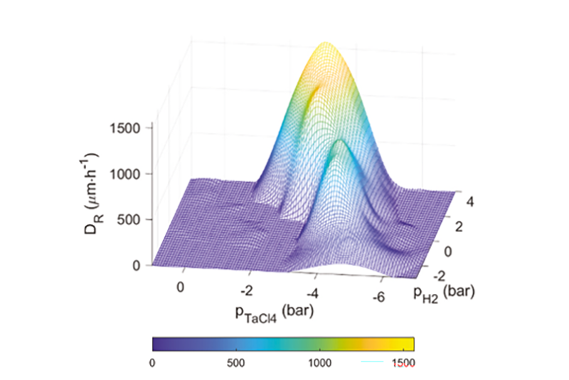
A 3D heatmap depicting the tantalum deposition rate (DR) as a function of the partial pressure of TaCl4 (pTaCl4) and hydrogen (H2) (pH2) in a bar are shown at high temperatures. Zero deposition rate is shown in blue, whereas the highest deposition rate is shown in yellow, as indicated by the colour bar at the bottom of the figure
© Crown owned copyright 2026/AWEThe tantalum deposition rate is represented by DR, while p(TaCl4) and p(H2) are the local partial pressures of TaCl4 and hydrogen, respectively. T is the local temperature. This kinetic map enables molecular-scale chemistry to be fed into the chamber-scale model.
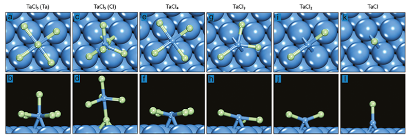
Schematic showing density functional theory-optimised top-down and side-on views of the most favourable adsorption geometries for the tantalum chloride complexes. Tantalum atoms are depicted by blue spheres and chlorine atoms depicted as light green spheres
© Crown owned copyright 2026/AWEConnecting the scales
The chemical kinetics were coarse-grained into the CFD digital twin. In practical terms, the CFD model determines the local temperature and gas composition in each relevant region of the chamber, while the kinetic model translates those conditions into a local deposition rate.
Gas flow and temperature influence the chemistry, but chemistry also influences the gas phase. TaCl5 and hydrogen are consumed at the surface, HCl is produced, and the deposit grows over time. These changes can affect concentration gradients and, over sufficiently long periods, may alter the way gas flows over the substrate.
The resulting model can therefore evolve the deposition process through time. It predicts where tantalum accumulates and how the thickness profile develops across a component, extending well beyond a single snapshot of the initial gas flow.
This ability to simulate deposition as it unfolds, rather than as a fixed, initial state, is particularly valuable for complex substrate geometries. A region directly exposed to fresh reactant flow may behave differently from a recessed or shielded surface.
A flow pattern that appears uniform at the scale of the complete chamber may still generate important variations close to the substrate.
By linking each scale, the model helps explain where and why differences occur. A variation in coating thickness can be traced back through the model to local reactant depletion, temperature, flow direction, or a specific feature of the surface chemistry.
Rooted in reality
A model’s reliability ultimately rests on how well it holds up against physical evidence, regardless of its sophistication. In collaboration with University College London (UCL) – as part of the AWE-UCL Chief Scientist Short Project Scheme – students carried out gas-phase DFT calculations during a summer internship programme. Researchers at UCL are also separately conducting targeted validation experiments in simplified flow environments using substrates with well-defined geometries, including disks, cylinders and spheres.
These experiments mean the chemical kinetics can be examined without the geometric complexity of the full industrial chamber. Temperature, flow and composition are controlled systematically, while deposition rates and thickness profiles are measured and compared with model predictions.
Beyond simply confirming agreement between the calculation and experiment at a single operating point, the experiments help us quantify uncertainty, establish error bounds and identify which parameters have the greatest influence on the result.
Parameter sensitivity analysis is especially useful. Some inputs vary without significantly changing the predicted coating, while others can have a disproportionate effect. Understanding that difference tells us where better measurements or more detailed calculations would provide the greatest benefit.
Once the chemical kinetics are benchmarked and uncertainties understood, they can be applied to the full chamber model with much greater confidence.
This combination of simulation and experiment is important. Modelling allows us to explore conditions that are difficult or costly to test directly, while experiments keep the model connected to reality.
A kinetic situation
The success of this project rests on the combination of several complementary techniques. Computational chemistry explains why the reaction occurs on the surface rather than in the gas phase. Kinetic Monte Carlo simulation turns a collection of elementary reactions into practical deposition rates. Computational fluid dynamics shows how the local chemical environment varies throughout a large and geometrically complex chamber. Carefully designed experiments provide validation, uncertainty estimates and confidence in the final predictions.
Although each method operates at a different scale, information is exchanged between the modellers and experimentalists who collaborate to test, refine and interpret the results.
Together, they connect the breaking of a single tantalum-chlorine bond with the thickness of a coating produced inside a multi-million-pound industrial facility. That is the real strength of multiscale modelling. It allows us to look simultaneously at the fine detail and the complete process, to understand the chemistry, predict the engineering consequences and make better informed decisions in the real world. Being able to better predict how tantalum coatings form before manufacture allows chamber configurations and operating condictions to be optimised for improved coating quality and uniformity.
With a validated multiscale model, the chamber becomes a space that can be explored virtually. We can investigate changes to the positions of inlets and outlets, adjust the relative and absolute flow rates of the starting materials, alter baffle configurations, and examine the effects of different operating temperatures. Each option can then be assessed across two measures – average deposition and the predicted uniformity of the thickness profile across the substrate.
These ‘what if’ questions are explored alongside discussions with the chamber operators and help us to understand how the system behaves in practice, and how their day-to-day experience compares with what the model predicts.
The UCL experiments keep the underlying chemistry grounded in reality, while the ongoing dialogue between modelling and operation ensures that virtual optimisation stays connected to how the chamber actually performs.
This allows design questions to be addressed before committing to physical modifications. It also makes it possible to examine interactions that might otherwise be missed. Moving an inlet, for example, could improve TaCl5 supply to one region, but alter mixing with hydrogen elsewhere. Increasing a flow rate may reduce reactant depletion, but change residence times or temperature distributions.
The multiscale model evaluates these effects as parts of one connected system. Through this approach, we have successfully fine-tuned important aspects of the chamber configuration and operating conditions. The work has helped improve product quality, reproducibility and process efficiency, while providing a much deeper understanding of the process itself.
Perhaps most importantly, the model is more than a one-off design tool. It provides a framework for investigating alternative substrates, operating conditions and chamber modifications. As experimental evidence becomes available, the kinetics can be refined and the digital twin updated.
In this case, the journey from molecules to manufacturing performance has delivered a practical tool for optimising an important industrial process, and shows what becomes possible when modelling, experiment and engineering are brought together.
Why is tantalum a key defence material?
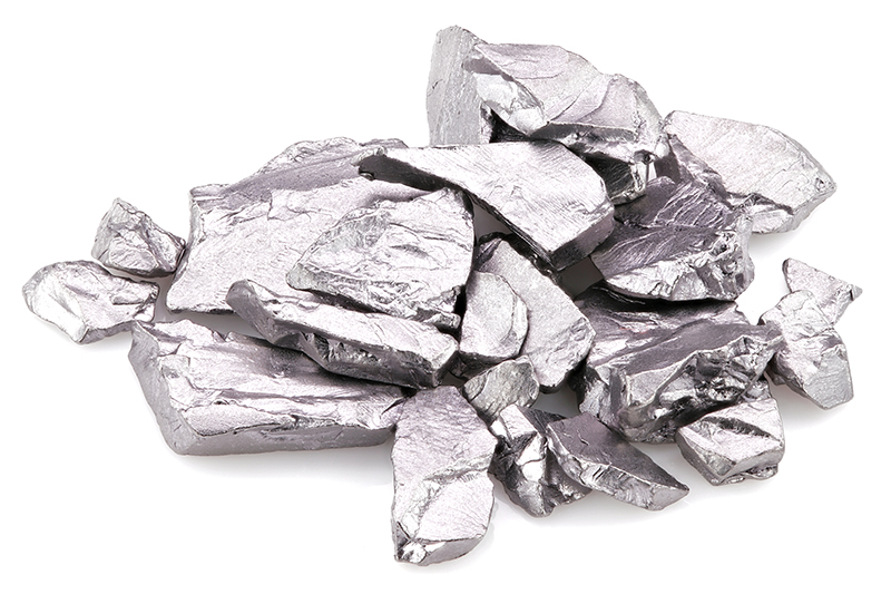
Tantalum’s physical and chemical properties enable broad usage in advanced technological and industrial sectors.
It is resistant to corrosion from a wide range of chemicals, has the fourth highest melting point among metals at 3,017°C, is a good thermal and electrical conductor with high resistance, is ductile, non-toxic to humans and around as twice as dense as steel.
Its ability to withstand extreme temperatures and resist corrosion is vital for components exposed to high-stress environments in engines. Additionally, tantalum is used in rocket nozzles and high-temperature furnace components, where both thermal stability and resistance to corrosion are essential.
Tantalum is incorporated into directed-energy weapons and railgun projectiles due to its high electrical conductivity and thermal stability.
It is preferred in military-grade capacitors over commercial equivalents due to its superior durability, shock resistance and extended service life. These are used in radar systems, communication devices, avionics and missile guidance systems, where reliability in harsh environments such as vibration, high temperatures and electromagnetic interference is essential.
Also, tantalum alloys enhance the penetration power of armour-piercing munitions, rivalling tungsten and depleted uranium in both density and self-sharpening capabilities. They are used in kinetic energy penetrators for tank and anti-tank rounds, as well as in explosively formed penetrators designed to defeat heavy armour. In naval applications, tantalum is also used to protect ships from saltwater degradation.
Source: www.samaterials.com/content/what-are-the-uses-of-tantalum.html; www.sfa-oxford.com/knowledge-and-insights/critical-minerals-in-low-carbon-and-future-technologies/critical-minerals-in-defence-and-national-security/
More like this...