Spotlight: How to inspect composite materials using laser shearography
Minton, Treharne & Davies Ltd., UK, Technical Director of Materials Science, Peter Moore, explains some of the basic theories behind testing composite materials using laser shearography.
The wide variety of materials currently available for use in composite manufacture, coupled with the potential complexity of the final structures, can present many inspection difficulties. Some traditional types of non-destructive testing (NDT) have limited relevance for the inspection of these materials.
Ultrasonic inspection has its uses, especially with phased array inspection and carefully selected sound frequencies, however, it undoubtedly has some limitations in terms of the material being inspected and the speed of inspection on large components. To further complicate matters, the wide range of potential defects from which composites can suffer also presents inspection and detection problems.
Laser shearography is an NDT inspection method highly applicable to composite inspection, which can detect a wide variety of surface and sub-surface defects.
It is an active test method as it measures the reaction of the inspected material to an applied stress. Laser shearography can be applied to a wide range of surface shapes, colours and textures and leaves no residues.
The elementals
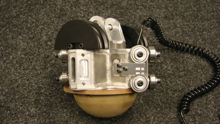
The basic principle of laser shearography involves inspection of the surface of a sample with a shearography camera which records an interferometric photo of the surface. This provides a ‘fingerprint’ of the roughness and shape of the surface in the unloaded state. The sample is then subject to a light stress. This can be accomplished in several ways, such as by flexing of the component, vibration, application of a vacuum hood or heat. For example, if heat is applied via a pulse from a halogen lamp, the surface will attempt to expand slightly.
If weak spots are present in the surface they will expand or deform more –although typically only at the micrometre or sub-micrometre level – than the surrounding good material. After application of the stressing method, a second interferometric photo is taken in the stressed, deformed state. In order to obtain information as to the differences in surface profile between the two states, the two interferometric photos are subtracted, which produces a shearogram.
In effect, a shearogram represents the topography of the changes in the surface between the unloaded and stressed states. In this landscape, the disturbed surface lying over defects typically appear as hills or valleys. Measurement of these features can provide information as to the defect size. The skill of the operator can help in the interpretation as to the nature of the defect, although such additional interpretation is often difficult and may not be possible in some applications.
Laser light and shearograms
The comparison of the two photographs is only made possible by the use of coherent, monochromatic laser light. When such light is shone onto a surface, variations in surface texture result in interference patterns, producing a visual speckle effect.
While changes in the profile of the surface would alter the speckle pattern, this alone would not provide useful information. In shearography the light entering the camera is sheared by two mirrors to create a double image. This double image means that each pixel of the CCD detector in the camera receives light from two different locations on the surface being viewed.
The separation distance and direction between these two locations is the shear vector. When the object is stressed, the two locations undergo motion relative to each other, altering the phase relationship of the light and changing the light intensity response at the camera. The difference in light before and after stressing will indicate surface displacement – variations in the displacement will indicate variations in manufacturing and/or defects.
Because the speckled pattern relates to interference between the waves in the reflected light, the final subtracted photograph typically consists of a characteristic pattern of black and white fringes.
In addition to local types of defects, an interpretation of the mechanical properties of the material can be also be made. If the material is mechanically weak the fringe pattern will display many close lines, which indicates the greater deformation of the surface.
This can be useful in identifying areas of poor construction. In one instance we detected such an area and the component was condemned. On disassembling the composite, the honeycomb core was found to be missing, it had been replaced with expanded polystyrene and rolled up newspapers.
To the skilled operator, a fringe pattern provides evidence about the relative deformation of the surface of the component between its two states – initial and stressed. Where there are no defects, the final image will be a pattern of wide, regular fringes. Where there is a subsurface defect, e.g. delamination, void or crack, or a disbond, the regular fringe pattern will be disturbed.
In addition, features of construction such as underlying variations in thickness or the presence of ribs or reinforcement will also result in visible changes to the final pattern.
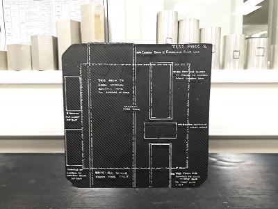
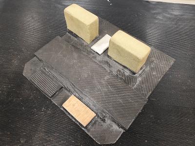
A skilled operator should be able to identify the size of defects within the structure, as well as possibly providing an opinion as to their nature and depth, depending on the material under test. Where possible, it is best practice to prepare a suitable comparison or calibration test piece for the operator to determine how various defects and construction features will appear under test in the component in question.
Practicalities of laser shearography
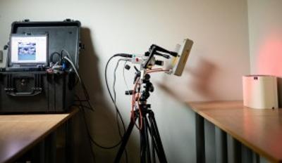
Laser shearography requires the use of lasers, cameras and computers. These normally require the operator to transport several boxes of kit for an inspection. The equipment is sealed against dust and moisture, and is usable in outdoor working environments. While laser light is used, it is low power with a low-risk classification.
Once set up, this inspection technique can inspect areas of approximately 1m2 per minute, allowing rapid inspection of large areas. Portable hoods with extraction pumps inspect individually smaller areas but have a fast cycle time, also resulting in the potential for wide-scale inspection.
A wide range of defect types can be detected by this method, including:
- Laminar unbonds - never bonded
- Disbonds - failed bonds
- Delaminations
- Inter-laminar separations
- Impact damage - barely visible impact damage
- Crushed core
- Internal corrosion/water ingress
- Irregular strain concentrations - weaknesses in bond quality, e.g. poor consolidation, and
- Changes in section and core splices/bulkheads.
At MTD we primarily use laser shearography for inspection in the aerospace, wind turbine and superyacht industries where large areas of a fuselage, wing or hull may need to be inspected. We typically inspect materials either after manufacture or after an impact where sub-surface damage is suspected.
However, laser shearography is not limited to these industries and we have used this inspection technique for a variety of materials in uses as diverse as Formula 1 racing to home insulation.