Probing the pipeline - understanding failures in flexible pipelines
Dr Alastair Houston MIMMM and Peter Moore MIMMM at Minton, Treharne & Davies Ltd, UK, on understanding failures in flexible pipelines.
The oil and gas exploration and extraction industries rely heavily on materials that must endure extreme environmental and in-service conditions. In many instances, the ideal properties of strength, flexibility, toughness, fatigue endurance and corrosion resistance are not available in a single material, and so composite structures that harness the best properties of different materials are used.
One such item is the flexible pipeline, or ‘flexible’. These flexibles can carry crude oil, gas, chemicals or seawater to or from the wells at great internal pressure. They can be attached to a rig, floating platform, or ship, and hang down to a hub or well head on the seafloor – flexibles are also used subsea within oil fields carrying fluids around and between different installations.
A flexible friend
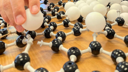
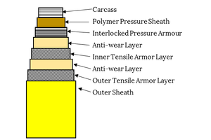
A flexible is a composite structure fabricated from layers of different materials. Depending upon the type of service,
the internal layer – the carcass – might be an austenitic stainless steel for crude extraction, or a polymer for seawater injection. This is followed by polymer pressure sheaths to retain the internal fluids, then an interlocking (but still flexible) high-strength steel armour layer, which provides hoop strength to contain the internal pressure.
Continuing outwards, there would typically be a layer of low-friction polymer tapes alternating with layers of steel tensile armour wires. These armour wire layers are wound in opposing spirals to balance their properties and carry the axial in-service loads.
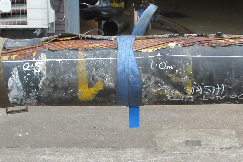
The external sheath is the outer most layer and is an all-encasing thick polymer tube to provide protection from the environment. A schematic showing this construction is shown in the image above. An exemplar failed flexible, awaiting dissection and investigation, is depicted in the top image.
As might be expected, there can occasionally be a failure in one of the layers, which, in the worst case, might result in an escape of fluids and give rise to the flexible having to be isolated and removed/replaced.
The range of failure modes that can befall these workhorse components is impressive and, as independent investigators, we have built up a wealth of experience in investigating them. In the following sections, we detail four typical examples.
Fatigue
Ask a materials expert what the most common type of mechanical failure is, and it is a good bet that they will say fatigue – whether it be the hip implant femoral head, the wind turbine gear tooth, or the wheel stud of the average family estate, fatigue is everywhere and, unfortunately, flexibles also suffer from fatigue.
In this example, a deep-water flexible broke near the connection where it hung from a floating platform, dropping the long flexible across the subsea infrastructure on the seafloor beneath.
When it was recovered, we had to analyse the 153 fracture surfaces on the tensile armour wires designed to support the weight of the flexible. This fractography revealed a complex pattern of fatigue stopping and starting at different points around the periphery of the line.
After detailed mapping and examination we determined that, at the outset, fatigue had initiated in many wires in the outermost tensile armour layer. Eventually, when one wire broke, the adjacent wires bore slightly higher loads, resulting in faster crack propagation, and shorter times to fracture. When approximately 10-15% of the outer wires had fractured, the dynamics of the system changed – the remaining outer armour wires unwound slightly, straightened and lengthened a little, which transferred much of the in-service loads to the inner wires.
The reduced loads on the outer wires caused their cracks to arrest, however, fatigue then initiated on the inner wires, at a location slightly removed from the outer wires fracture sites. As the inner wires fatigued and the number of fractures accumulated, the remaining inner wires unwound and lengthened, and the dynamic switched back again to the outer wires. This back and forth continued until the intact wires were too few to sustain the loads and final rapid failure of the entire flexible pipeline occurred.
Overall, we determined that the cause of the failure was the horizontal and vertical movement of the flexible hanging in the sea, combined with the load of supporting its own mass and the liquid contents, which initiated fatigue failures in the outer wires over many years of service.
Hydrogen sulphide and sulphur corrosion
While we refer to the inner polymer sheaths acting as a pressure barrier, small-molecule gases can, over time, permeate through the pressure sheath and accumulate in the annulus between the pressure and outer sheaths. This can have various implications depending on the gases involved, but one of the most critical is hydrogen sulphide, primarily from sour oil and gas but also potentially from anaerobic bacteria.
Hydrogen sulphide can lead to enhanced corrosion rates and, critically, sulphide stress cracking (SSC) of high-strength carbon steels – the very types of steel used as pressure and tensile armours.
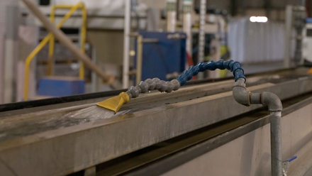
Because of the potential for gas accumulation in the annulus, flexibles are fitted with small breather tubes that connect to pressure release valves – allowing for the permeated gases to vent, rather than accumulate and risk a rupture of the outer sheath.
We dissected a failed riser that displayed numerous wire breaks in close proximity to a breather tube, as shown in the image overleaf. The wires in this area were blackened and displayed torsional fractures. Analysis of the wire-ends using energy dispersive X-ray spectroscopy (EDX) indicated the presence of iron sulphide, and fractography determined that these were brittle fractures. While this was clearly an SSC failure, the question remained as to why it was so localised?
Testing of the pressure relief valve fitted to the breather tube revealed that it had been opening under very low pressures, allowing some seawater to seep in. The presence of water and trace levels of chlorides had locally exacerbated both corrosion and SSC, resulting in failure of the tensile wires, and precipitating a chain of events that resulted in the loss of pressure containment.
As such, the improper operation of the breather valve, and its admission of small quantities of water into the flexible, was determined to be the root cause of this failure.
Microbiological corrosion
In seawater injection, seawater is pumped into a well at high pressure – perhaps 100-400bar depending on circumstances. The construction of a seawater injection flexible is much the same as that for crude extraction, with the exception that the carcass is typically a polymeric sheath. This sheath is secured at the ends into a large, metallic end-fitting with a cone, made from a corrosion resistant alloy (CRA) containing high percentages of chromium and nickel.
In normal circumstances, such a strong and corrosion-resistant material is ideal for the aggressive seawater environment. However, if the seawater is not treated with a biocide, bacterial colonies can establish themselves.
In this case, a seawater injection flexible was locked in and remained stagnant for a period of several months. When re-pressurised, the cone securing the sheath collapsed, and seawater passed around the end of the sheath, through the overlying steel wire layers and burst the external sheath.
Inspection of the cone (shown in the image below) revealed an area of severe pitting corrosion in which the cone had locally lost 95% of the section thickness. Material analysis and microstructural inspection determined that the CRA was of the expected, corrosion-resistant quality. EDX analysis detected sulphur in the corroded areas. Swabs taken from the corroded areas were analysed for DNA, and known species of microbial- induced corrosion (MIC), causing sulphate-reducing bacteria (SRB), were detected within the corrosion pits.
As such, MIC was determined as the proximate cause of the failure. Investigation of dosing records revealed that the seawater in the line was not adequately treated with biocide prior to the shutdown, as such the failure to dose was deemed the root cause.
Polymer problems
One of the polymers used extensively in pressure sheaths in flexibles is polyvinylidene fluoride (PVDF). This is a robust and proven material both at resisting the many and varied fluids within the pipelines, but also at being able to accommodate movement and flexing of the pipeline with little creep or movement.
Unusually for a polymer, PVDF can exist in five different crystalline phases, depending on the processing methods used during manufacture. This can result in unusual properties if variations in manufacturing result in the presence of unexpected phases.
In this case, a series of long flexible pipelines suffered multiple failures when pressure tested. When dissected, the leaks were found to be associated with through-thickness circumferential fatigue cracks in the PVDF pressure sheath, with dozens of such cracks ranging from sub-millimetre to a few millimetres in length being found in every metre of the pipeline.
The image opposite shows an exemplar fatigue crack. Initially, chemical attack was suspected as the root cause, but no aggressive chemical residues were detected, nor the cross-linking characteristic of such an attack.
Detailed testing and analysis by differential scanning calorimetry and Fourier transform infrared spectroscopy determined that rather than being manufactured from the normal alpha phase, the PVDF contained around 50% β phase, indicative of high stresses during manufacturing. The high stresses and β phase had assisted in the initiation and propagation of fatigue cracks.
Comparative measurements of the various layers in the as-received and relaxed condition indicated that the PVDF had been stretched by 5.6% during manufacture. When, eventually, manufacturing records were released, these were interrogated, and revealed a 5.5% over-extension – a rewarding corroboration of our laboratory results. This therefore confirmed that damages (over-extension) during manufacturing were the root cause of this failure.
Conductivity changes
The technology and materials used in flexible pipelines cross over with those used in flexible control and flexible power cables. While the failures we have discussed above all resulted in the loss of mechanical integrity, ‘failure’ can be a broader term to refer to non-catastrophic incidents.
For example, a reduction in conductivity would also constitute a ‘failure’ of metallic components in a power-carrying environment.
We were tasked with conducting bespoke fatigue testing of the copper screens within flexible subsea power cables to investigate how they changed over time. This was delicate work looking for their conductivity changes in the range of a few milli-ohms.
We constructed a test rig in which complete cables were cycled to replicate light bending movement. Rather than the slow accumulation of damages and a gradual deterioration in conductivity, we detected a step change in the screens’ conductivity. Dissection and microscopic inspection of the tested cables revealed that the step changes were associated with the onset of cracking in a longitudinal weld used to secure the copper sheet into a cylinder around the cable, as shown in the figure below.
In the pipeline?
Flexible pipelines are complex technical structures that provide robust service in many environments, however, like all engineering components, they can experience failure due to unforeseen or adverse conditions. Investigation and study of these failures can help manufacturers and users to better understand why problems arise, and prevent or mitigate the risk of future occurrences.
See a profile of Alastair Houston, a member of the IOM3 Student & Early Career Committee.