Don’t step on the cracks - testing for environmentally assisted cracking
Joy Sumner MIMMM, Andrew Potter and Stefano Mori at Cranfield University, UK, on the array of techniques used to test for environmentally assisted cracking.
No one wants to see plant failures, and certainly not unexpectedly. However, environmentally assisted cracking (EAC) is, unfortunately, synonymous with unexpected failure.
EAC typically occurs anytime that a susceptible material is placed into a detrimental environment while experiencing stress – this class of damage mechanisms can be activated under operating conditions that mechanical analysis has otherwise indicated ‘safe’, and includes mechanisms such as stress corrosion cracking (SCC) and corrosion-fatigue (CF). As such, interest in these mechanisms arises in multiple fields, from the failure analyst trying to learn from an unpleasant experience, through to researchers addressing hypothetical damage mechanisms which may occur as existing materials are employed in novel operating environments.
To understand more about the problem, it is necessary to consider the environment in which a given component will operate and the stress that it is under. From there, an assessment of EAC risk can be made and, if needed, testing programmes can be deployed before steps can be taken to minimise that risk, for example, by changing the material, its geometry, or limiting the operating environment.
EAC is highly dependent upon the specifics of a material’s use. Alloys which are susceptible in one environment may be perfectly stable in another. A classic example of this is the vulnerability of copper-based alloys, including brasses, to ammonia-containing solutions – something which it seems should be easily engineered around – simply don’t use these alloys where you expect to encounter ammonia. In practice, aquatic organisms can generate the relevant solutions, meaning that pipework and vessels in which living matter can be trapped can become vulnerable, even if nominally containing and transporting other fluids.
Another case, well known from the oil and gas field, is the susceptibility of high-strength steels to sulphide-rich production fluids. This is commonly known as sulphide stress cracking, where the hydrogen sulphide within the production fluid can result in high hydrogen activity (hence commonly being referred to as sulphide stress cracking).
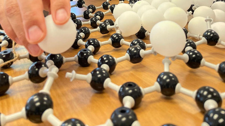
Hydrogen can have a profound effect on vulnerable alloys, such as high-strength steels, embrittling the material and leaving it susceptible to stresses. In this hydrogen embrittlement, atomic hydrogen can rapidly adsorp on the surface and diffuse into steels, recombining into molecular hydrogen at defects and locally raising stresses while also reducing ductility. This is a current area of active research interest for those involved in the developing hydrogen economy.
Many of these interactions can be looked up, for example, in the NACE Corrosion Engineer’s Handbook, but questions remain for industry and academia when considering novel environments. What happens when operating conditions are less well understood, or potentially even unique?
The other parameter driving EAC is the presence of tensile stresses. When considering stress, it is tempting to link this to the applied load that a component experiences.
Considering the hydrogen embrittlement related challenge as an example, cleaning oils from parent metals and baking filler materials to remove water from the surface has been a long-standing practice to minimise the contamination of the weld as well as the embrittlement of the underlying material. It also reduces locked-in residual stresses that can result, irrespective of applied loads.
In stress corrosion cracking (SCC), the material’s properties – such as ductility/hardness – can be altered, leaving apparently ‘safe’ materials susceptible to cracking. The impact of the exposure environment on the underlying material’s properties can, either locally or generally, impact its ability to withstand crack growth. Typically, the resultant crack is highly branched, either following pathways along grain boundaries (SCC) or through them (transgranular SCC).
Stress corrosion cracking, however, is not the only mechanism. Many applications will involve more varied classes of stress.
For example, an offshore structure experiencing wind and wave action will see cyclic application of loads that are below the material’s yield stress, but could start to propagate fatigue.
The consequences of this may be exacerbated if the material is in some way suffering a degradation in its properties, as can occur when placed in specific environments – microbial activity, among other factors, can generate local concentrations of chemicals. In this instance, the concern would be for corrosion-fatigue.
Corrosion-fatigue damage is characterised by cracks linked back to an initiation point, either at the surface or within the material. These initiation sites are formed through scratches/impact, design, manufacturing-related porosity/inclusions, or chemical attack.
As the mechanism advances, the crack advances as the local tensile stress cycle, pausing when the magnitude of the stress cycle falls, leading to a distinctive pattern of ‘beach marks’ following ‘thumb nail’ crescents, until the component ultimately overloads and fails.
Unlike ‘pure’ fatigue, it should be noted that the operating environment can lead to corrosion or oxidation within the propagation fatigue crack, potentially obscuring these distinctive marks.
A variant of this corrosion-fatigue mechanism might see cracking of the weld for a pipe that transports high-temperature working fluids. If the plant shuts down regularly, as is increasingly common in power plants, then the temperature within the pipe will drop, leading to a coefficient-of-thermal-expansion driven contraction, and a change in the local stress state. With repeated start-ups and shutdowns, the application of a cyclic stress driven by temperature changes leaves the plant and, in particular, its welds, which have different materials properties, vulnerable to thermo-mechanical fatigue (TMF).
Targeting tensile stress
As confidence has grown in materials use at the extremes of their operating conditions, so too has the importance of research into EAC mechanisms. Due to the variation in applied tensile stresses and material exposure routes from one application to another, modelling is often targeted to specific conditions – some failure mechanisms may be triggered by the local breakdown of a protective film, initiating a fatigue-inducing pit, while others are driven by the environment embrittling material surrounding that damage initiation point.
One key aspect of all these stress-related examples is its tensile aspect. This applied tensile stress can be intermittent or long term, localised, or residual, but its presence is key to all EAC mechanisms.
As such, when running testing programmes to understand EAC, it is key to consider how this stress is applied, and how the material is treated to ensure that it has been ‘exposed’ to real or simulated anticipated operating conditions. Due to the variation in mechanisms covered in EAC, there are many different laboratory test methodologies.
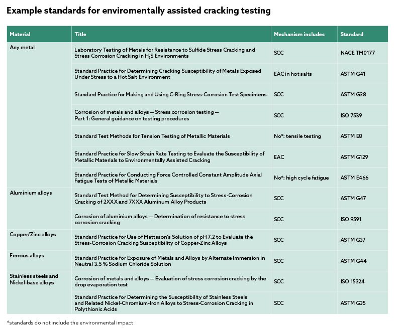
To help control and minimise the risk of EAC, testing can be carried out. A number of standards exist to help facilitate this (see table above). Reviewing current research shows a wide range of different test set-ups and sample geometries. However, these standards do not always cover the combination of stress/material/exposure environment of interest to the potential challenge at hand. As such, the most important step is establishing the likely cause of any potential deterioration. Commonly asked questions to facilitate this involve:
- Has this problem been seen in industry before and, if so, what is the morphology of the failure?
- If a material is being used in a novel environment (in terms of chemistry, temperature, pressure, etc.), can that exposure condition be expected to have an influence on the material’s performance?
- If there is likely to be a component of tensile strain in the system, is this constant or cyclic?
Beneath the surface
Stress corrosion cracking has been investigated in fields ranging from pipeline structures in subsea conditions, to weld safety in nuclear waste storage, and the suitability of superalloys for gas turbine use.
Assessing SCC through testing involves generating the correct stress state and exposure conditions. There are a number of commonly employed sample geometries, each of which results in a different stress field within the sample.
Common tests include the use of tensile testing samples (uniaxial stress field), bent beams (multi-axial high von Mises), C-ring samples (multi-axial high stress gradient) shown in the image opposite left, double cantilever beams (complex stress states), or slow strain rate testing (uniaxial stress field).
In all of these instances, the intention is to apply stress to a sample that has either been pre-exposed or, ideally, is still immersed in representative exposure conditions.
C-ring testing can be one of the simplest methods. A small ring of material is produced (or a pipe section cut down) with a missing segment. Holes are added to the C-ring on an axis perpendicular to the gap, through which a bolt can be added. Tightening the bolt applies stress to the sample, reaching its highest value opposite the ring’s opening.
In this stressed state, the sample can then be exposed in a representative environment, with the bolt being periodically examined to ensure no relaxation has occurred.
Common parameters for control include any pre-exposure either of the ‘ready to test’ sample, or the material that samples will later be machined from; the use of aged materials; confirmation of the displacement required by the bolt (often accompanied by finite element analysis modelling, although simple, approximate formulae exist in the standards); consideration of factors such as gas/fluid flow rate and test pressure/temperature; and confirmation that the experimental set-up is correctly electrically isolated to prevent galvanic corrosion.
By varying exposure conditions or stress states, the differing response of a material from its baseline operation can be determined.
Talking about turbines
Currently corrosion-fatigue is of interest in applications including superalloy blades in industrial gas turbines and structural steels for offshore wind turbines.
In corrosion-fatigue, where corrosion acts to limit the fatigue resistance of a material, testing often focuses around placing new or pre-corroded samples into a fatigue rig, ideally with a local controlled environment to simulate the conditions of interest, so that data can be compared to a fatigue-only baseline.
Common outputs are S-N curves – reporting ‘N’ cycles to failure at a maximum ‘S’ stress – where the additional impact of corrosion is shown to reduce the number of cycles to failure, and potentially eliminates any safe fatigue limit below which stress the material would normally be considered unsusceptible to fatigue.
Within this corrosion-fatigue testing methodology, a number of different parameters can be tuned – the sample geometry including whether or not a sample starts with an initial ‘notch’ from which fatigue can nucleate; the sample material, i.e. alloy, heat-treatment, surface finish and crystallographic orientation; whether or not to pre-corrode the sample; the ‘waveform’ of the applied load both in terms of how long each stage of the cycle is, and the shape of this cycle (sinusoidal, sawtooth and trapezoidal have all been used); R-ratio relating the maximum applied load and minimum applied load for each cycle; exposure temperature; etc.
Testing work is usually carried out on a load- or strain-controlled frame. Confirming the most suitable parameters for study can be addressed through academic and industrial partnerships, with the ultimate aim of reproducing the corrosion-fatigue morphologies seen in operation, validating the testing findings.
Continuing challengeResearch and application of knowledge related to EAC continues to be an important research area. The range of ways in which materials can be degraded by the combined action of stress and environment is immense, as is the ever-changing nature of industrial challenges – be that in terms of operating environments, plant life extension, or cycling of operating conditions. Far from having been ‘solved’, this family of failure mechanisms will continue to be of interest in the foreseeable future.