Testing times - the challenges of additive manufacturing for mechanical testing
Metal additive manufacturing is a young technology with plenty of potential, yet challenges exist around its mechanical testing.
Jimmy Campbell, Chief Technology Officer at Plastometrex, UK, builds a picture of current methods.
Metal additive manufacturing (AM) is set to revolutionise the manufacturing sector. The method provides several advantages over traditional techniques. It provides much more design freedom, allowing radical design innovation. This gives engineers the ability to create parts that simply could not be manufactured previously. Additive manufacturing can also be used to accelerate the design process with rapid prototyping and, in the right applications, it can reduce tooling costs, time to market, production costs, waste and emissions.
Furthermore, the metal AM market is expected to continue growing at a compound annual growth rate of 20%, according to PwC’s 2019 report, Metals 3D printing closing the cost gap and getting to value.
However, as a young technology, AM is not without its challenges. Mechanical testing is one area. The gold-standard for mechanical testing is the tensile test, which measures the stress-strain properties of materials, including the yield stress and ultimate tensile strength (UTS). This test involves machining of a large test coupon and requires access to a universal mechanical test machine. Although widely used, the tensile test can be time-consuming and cumbersome even for materials manufactured using traditional subtractive techniques, with testing turnaround times of hours or even several days if outsourced, and the machinery and capital set-up costs are high.
The test also necessitates the destruction of the sample, and the generation of large amounts of wasted material both to create the sample and in the form of the sample itself.
With materials made by AM, there are extra complications which make tensile testing even more difficult. Metal AM parts often show anisotropy, where properties are different in different orientations, and therefore multiple tensile test specimens are required to fully characterise the material.
The parts can also be heterogeneous, with different regions having different mechanical properties due to the thermo-mechanical processing history of the sample. With even the smallest tensile specimen sizes recommended in internationally recognised standards, such as ISO 6892-1 or ASTM E8, the coupon must be several tens of millimetres. Therefore, if properties vary over just a few millimetres, it is almost impossible to capture these variations.
Finally, some of the parts produced are simply too small for tensile specimens to be cut from them. In these cases, mechanically qualifying parts can be extremely challenging. It is for these reasons that the 2017 UK Additive Manufacturing Strategy report recommended that there is a need to develop mechanical testing processes suitable for AM to enable ‘fit for purpose’ evaluation’.
Put to the test
An alternative to tensile testing, which is also in common use is the hardness test, where a hard indenter of a well-defined shape is pushed with a known force into the surface of a material. The indentʼs diameter is then measured using an optical microscope – together with the applied load and indenter geometry, this can be used to calculate a hardness number.
The test is quick and only requires simple metallographic preparation. However, hardness is not a fundamental material property, as changing the indenter geometry or the applied load will change the hardness number. In addition, there is no universal or accurate method to calculate yield stress or UTS values from a hardness test. Hardness therefore can be used to map property variations, but the numbers obtained from this test technique are of limited engineering utility.
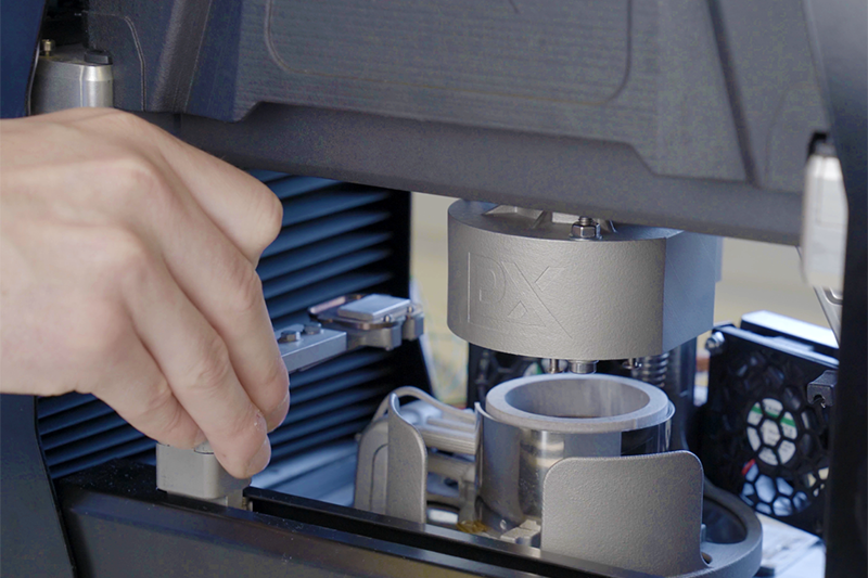
Profilometry-based Indentation Plastometry (PIP) testing is a new indentation-based technology that combines the simplicity and ease-of-use of hardness testing, while obtaining full-stress strain curves (including yield stress and UTS) previously only accessible through tensile testing.
PIP uses a large spherical indenter (typically a 1mm radius) and creates indents with a depth between 10-20% of the indenter radius. Indents are therefore typically around 1mm in diameter. With this scale of indentation, for most engineering metals, a ‘bulk’ response is achieved, i.e. all the microstructural features that give the metal its mechanical properties, such as grain size, grain boundaries, precipitates, second phases and many others, are captured in the indentation response.
Once the indent has been created, the shape of the indent is scanned using a profilometer which captures both the depth of indentation and the pile-up region around the rim of the indent.
Capturing the full indentation profile gives much more information than measuring just the diameter, as is typically done in a hardness test. The profile, together with the maximum applied load, is then analysed using an inverse finite element method (FEM) algorithm, which calculates the (true) stress-strain curve, including the yield stress.
Simple analytical equations can then be used to convert this curve to give the nominal (or engineering) stress-strain curve which includes the UTS. The testing is carried out on an Indentation Plastometer and all of the testing protocols are automated, allowing a full stress-strain curve to be obtained in less than five minutes.
Full metal
In his group at the University of Oxford, UK, Professor Roger Reed and his team are designing new alloys for metal AM applications. In this case study, the goal was to determine whether the PIP technology could substitute tensile testing for the accurate measurement of stress-strain curves and determine whether any anisotropy in the material could be detected.
An ABD-850AM nickel-based alloy was used for the current study. The material was first atomised into powder using argon gas. The particles had a median diameter of about 30μm. The AM method of laser powder bed fusion (LPBF) was used in this case, where a laser is used to fuse each subsequent layer together and carried out on a Renishaw AM400 machine. The layer thickness was around 30μm and laser power 200W with a traverse speed of 1.2ms-1.
Electron backscatter diffraction (EBSD) scans (shown in the image below) illustrate that the material exhibits a columnar grain structure. In the transverse x-y section, the grain size is relatively small (~30-40μm) and approximately isotropic. In the axial x-z section, the structure exhibits grain shape anisotropy. The grains are elongated in the build z direction and show strong <100> type texture.
The mechanical properties of this material were measured using conventional tensile testing and using the novel PIP technique. For tensile testing, both vertical and horizontal samples were required, while a small cube of 10x10x5mm was used for PIP testing.
PIP testing in the x-y isotropic plane showed excellent agreement with the directionally averaged response from conventional tensile testing (shown in the image below), sitting almost exactly between the extremes of the vertical and horizontal tensile test.
These results show PIP testing to be within just a few per cent of the averaged tensile curves for both yield and UTS values. Unlike uniaxial testing where, as the name suggests, all the straining occurs in a single direction, PIP testing will always produce a direction averaged response as strains in the material extend in all directions, both along the indentation axis and in the radial directions.
PIP testing in the x-z plane (which showed grain shape anisotropy) produced a non-radially symmetric residual profile shape. Here, there are clear differences between the apparent ‘diameter’ in the x and z directions.
The nature of the differences is consistent with the tensile test outcomes, with the material being ‘harder’ in the horizontal direction than in the vertical. So, while PIP-inferred stress-strain data cannot be produced in this plane, the procedure, which is very quick and easy to carry out, can be used to test for the presence of anisotropy and to obtain what might be regarded as a semi-quantitative measure of its nature and strength.
The information gathered from PIP testing enables the alloy development team to minimise their sample size, helping to reduce the amount of feedstock powder needed to screen new alloy systems. It will also allow them to avoid the need for machining tensile test coupons, reducing the time and costs associated with plasticity testing. Combined, these advantages allow the team to develop and rapidly validate new alloys with lower material costs than others still using conventional methods.
Further investigation
Looking forward, the Plastometrex Chief Technology Officer has recently been awarded a UK Research and Innovation Future Leaders Fellowship to further develop the technology to determine anisotropic stress-strain curves from indentation. This will extend the possible applications in the AM space, where anisotropy is commonly observed.
Plastometrex is also developing a high-temperature set-up,which will allow PIP to be used on metallic materials up to 800°C. The company has also received Innovate UK grant funding to develop a portable system, so it can be deployed on high-value assets in the field.
Also log-in to the Materials World e-zine to view an IOM3 Inform webinar on indentation plastometry and other metal plasticity testing technology.