Spotlight: Investigating Failure
What are the mysteries behind material failure? Jeremy Allen MIMMM, Consultant Materials Scientist at Minton, Treharne & Davies Ltd, in Cardiff, UK, plots the investigative process.
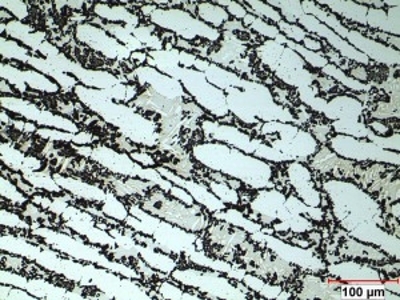
Etched micrograph of sigma phase formation (dark phases) in a super duplex stainless steel
© Minton, Treharne & Davies LtdIt is a fact of life that some materials and structures do not behave as expected, and premature in-service failure occurs. This is when we need to investigate to define the root cause.
All failure investigations are different, however, the underlying procedures are very similar, with adaptations made to suit the specific requirements of each case. Investigators must approach each incident open-mindedly and be flexible in their methods as the investigation develops. This means that different and often new approaches are needed at each stage, along with bespoke testing methods and equipment.
Diligent about documentation
A typical investigation of a material, component or system failure usually starts with a review of the historical and recent information pertaining to the component, its application and service environment. This often involves studying a myriad of electronic and hard-copy documents, data and digital photographs – in extreme cases, we have received up to 250 lever-arch files full of hard-copy, or tens of gigabytes as the electronic equivalent. Although, at the other end of the scale, a few notes or photographs might be all that is available.
This information is normally reviewed up-front, but it is not unusual for there to be a steady supply of additional documents throughout the investigation. Every document must be reviewed to ensure that nothing is overlooked. In conjunction with, and to supplement the supplied data, a literature search is normally conducted to identify relevant research papers, textbooks, test cases, specifications and standards.
Initial examination
The next stage is examining the failed component(s) or samples of them and, ideally, comparing them to intact materials. In many cases, this involves travelling to the incident site, which could be anywhere in the world, especially if the failure occurs in a large construction project, a remote pipeline or on a ship at sea – all of which would be impractical to transport to a laboratory.
Once onsite – and having been approved to work by the local site health and safety regulations – the failed component(s) are examined, which involves making a detailed catalogue of data including many high-resolution digital photographs, characterising the point of failure, the working and in-service conditions, and the environment.
Talking with the onsite staff, developing relationships and local personnel management is a key factor in learning the history of a failure – even if there is a language barrier. Ideally, if samples can be extracted, these will be transported to the laboratory for in-depth analysis and testing.
Nature of failure
Laboratory analysis and testing of samples is a major part of the investigative process, and includes a range of non-destructive and destructive tests to attempt to determine the nature of the failure.
Non-destructive testing (NDT) often provide useful information about a component before destructive tests are undertaken and can help to determine what additional tests need to be performed or the best location for a sample to be taken.
A typical (initial) NDT might be radiography (RT), ultrasonics (UT) or laser shearography (LS) to investigate the sub-surface condition of a component. Alternatively, liquid penetrant inspection (LPI) or magnetic particle inspection (MPI) might be used to determine the extent of a surface breaking crack.

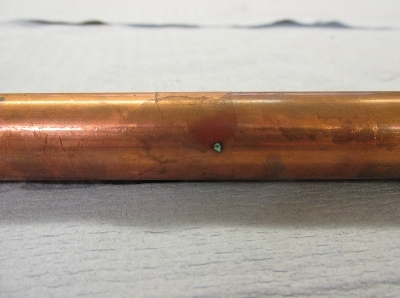
Pictured are visual and radiographic images of a 15mm-diameter copper pipe from a cold-water system that had suffered from type 1 copper corrosion, exacerbated by microbially-induced corrosion. The external indications were a few tiny pinholes, but radiography revealed larger (dark) areas where corrosion had occurred, showing that the internal corrosion was far more extensive than the initial visual examination suggested.
Destructive and physical testing typically occurs after NDT and provides good insight into a material’s physical properties. Such tests could include tensile testing, impact tests, hardness measurement, surface topography and fatigue testing – all in accordance with defined specifications.
Sometimes a bespoke testing programme is required. An example of a recent test method which we developed as part of a legal case was to assess the compressive load required to crush marble-sized agglomerated particulate material. We had to construct a suitable compression test rig and to generate agglomerated samples. Our results indicate that a maximum force of 80 Newtons (N) is required to crush the samples. However, what does 80N mean to a person? To say something failed at 80N is not a particularly tangible statement. How can a force of 80N be translated into a relatable quantity? To better facilitate understanding, we compared it to the real-world compressive properties of some well-known everyday items, such as cheesy puffs, seedless grapes, Maltesers and chicken stock cubes. The results we obtained are given in the table below. We were able to demonstrate that the agglomerated particulate material was not strongly bonded and required a similar crushing force to that of a chicken stock cube.
Visual analysis methods such as microscopy and fractography are used to analyse a material’s microstructure and the fracture surfaces of a failed component. These test methods are nearly always employed, and it is up to the experience and skill of the investigator to select the methods and regions for visual analysis. There is nothing quite so useful as being able to examine something in fine detail to locate the source of a crack or defect.
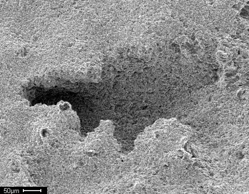
Initial analysis may be visual or include low-power microscopy, typically up to x50, followed by increased magnification inspection using reflected light microscopy (RLM) and, where necessary, scanning electron microscopy (SEM). Illustrated on p48 are a metallurgical micrograph and above is an SEM image. The micrograph (RLM) is a super duplex stainless steel which, despite having the correct alloy composition for its application, suffered severe premature corrosion. The microstructure contains abundant sigma phase formation at the grain boundaries, as a result of incorrect heat treatment during manufacturing, shown by the black threads between the pale austenite and grey ferrite. This undesirable phase renders the material susceptible to corrosion. The SEM image meanwhile, shows, the surface of a 304L stainless steel component which suffered from cavitation erosion.
The test methods described above are frequently supplemented with further analysis techniques such as energy dispersive X-ray spectroscopy, fourier transform infra-Red (FTIR) spectroscopy, dynamic mechanical thermal analysis (DMTA), optical emission spectrometry (OES), inductively coupled plasma optical emission spectroscopy (ICP-OES) and DNA analysis, which indicates the presence of bacterial species associated with microbial corrosion. Not all of these may be used, the relevant test methods are determined by the materials involved and the nature of the failure.
In combination, a suite of non-destructive, destructive and inspection-based tests act as a powerful tool to compile a complete profile of the material, the environment and the failure mode.
Reporting the results
Finally, a full report is compiled, describing the findings from the data review, the site visit, the NDT, the mechanical testing, the microscopy/fractography and any further analyses. Conclusions can then be drawn as to the failure cause and the underlying reasons. The reports we issue are frequently used as evidence in legal proceedings and consultants attend to present their reports and evidence as expert witnesses.