Meeting future emission standards
Jörg Feist and Silvia Araguás-Rodríguez of Imperial College spin-out, Sensor Coatings Systems, discuss how luminescent materials could help reduce emissions in automotive and gas turbines.
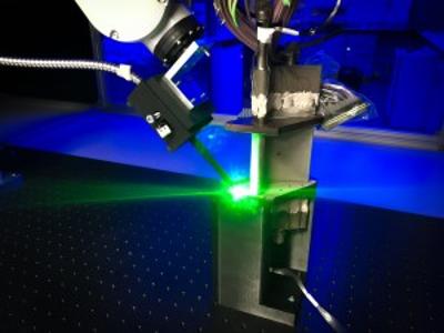
Whenever we jump on a plane or put our foot down on an accelerator to make a turbocharger work harder, we’re making that fuel burn at high temperatures. More stringent legislation will aim at reducing emissions, specifically CO₂. This can be achieved by operating the engine at higher temperatures, for different reasons though. The complexity of today’s engine designs, however, require much more advanced temperature monitoring tools to aid the component designer when operating at higher temperatures.
A recent invention based on luminescent materials uses paints and coatings which can memorise temperature profiles that can be read out after operation. The technology, in combination with robotics, enables the rapid digitisation of entire thermal maps across complex components. A significant step forward for designers building the engines of the future.
Some of you may be familiar with those luminescent glow-in-the-dark stars that often feature in children’s bedrooms. During the night, the intensity of the afterglow will become weaker and after a few hours the phosphorescence will cease entirely. Scientifically, this property of diminishing intensity is called lifetime decay and this type of process can be found in other natural phenomena such as radioactive decays.
Phosphorescence lifetime decays can last from nanoseconds to several hours as in the case of glow-in-the-dark stars and should not be confused with fluorescent processes which are much faster. Engineers in the field know that this process is temperature dependent and consequently can be used as an indicator of temperature. With increasing material temperature, the decay becomes faster, meaning the phosphorescence disappears quicker and this can be measured.
For several decades, the technology called phosphor thermometry has been developed for in situ online measurements in combustion environments such as automotive engines and gas turbines. Phosphor thermometry targets applications where other temperature measurement tools struggle to deliver reliable results. Phosphor thermometry needs to see the area of interest during operation as this is an optical technique that means means drilling optical ports into the machinery. This is not always practical, is often invasive and can be very costly. Hence, the technology is easier used in controlled research laboratories rather than realistic industrial applications.
Thermal history technology
Over the last decade, Sensor Coating Systems (SCS) has taken a different approach and developed thermographic phosphor materials with temperature memory capabilities. Again, the phosphorescent afterglow property plays a critical role in the detection of temperature.
The phosphorescent material is manufactured so that its structure gradually changes as it is exposed to increasingly higher temperatures and, once cooled down to room temperature, the afterglow will have permanently changed too. When applied over a component surface as a thin coating, different regions will see different exposure temperatures. This means that the material structure, and therefore phosphorescent lifetime decay, will then locally and non-reversibly change. Once the component has cooled down to room temperature, the changes in the detected lifetime decay in each region can be correlated to the temperature experienced by the material.
This temperature memory effect is accomplished by producing custom-designed phosphorescent pigments. The pigments are made through a solution processing method and consist of oxide ceramics manufactured with a very low concentration of phosphorescent ions – these ions provide the afterglow effect. From here, two different variants of application exist to target different areas. The pigments can be deposited either in the form of a paint by mixing the pigment with a liquid binder, or a robust coating, whereby the pigment is deposited through air plasma spraying. Whether as a paint or a coating, this temperature sensor is applied as a thin layer of 30μm and must be deposited so that its structure, and therefore phosphorescent properties, will gradually change with increasing temperature.
This technology significantly deviates from the way temperature information was historically gathered. Engine components treated with thermal history material are looked at after operation, as opposed to during operation. But with this new approach, can be gathered across the entire surface at locations that are usually inaccessible as it does not require any additional equipment, cabling or access while the engine is running. This makes the technology less intrusive, less risky and more powerful when it comes to the amount of data gathered. To maximise the data quality and volume, the smart materials are combined with automation equipment and portable instrumentation that can quickly and accurately perform measurements across a full component surface in a matter of hours.
The equipment also allows for pre-programming of measurement locations enabling high spatial resolution. Data is provided in a digitised format providing co-ordinates and the associated temperatures. A digital format also makes it easier to compare measurements, thermal simulations and designs, speeding up the design process. Temperature measurement capability depends on operating conditions but can be roughly defined as between 150oC and 1,600oC referring to our latest research.
Better data for industry
Industrial needs frequently drive the development of novel temperature measurement tools. During the industrial revolution, the need to produce steel in high quantities with reproducible standards was possible with thermocouples, a pair of welded metal alloy wires. The measurable electronic signal between the two wires changes with temperature. This replaced the calibrated eyeballs of a traditional blacksmith looking at the red-hot metal when working with it.
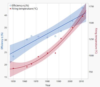
Today’s progress in gas turbines – for both jet engines and power generation is driven by the need for higher fuel efficiency and lower CO₂ emissions. Thermodynamically, a higher efficiency can be achieved by increasing the firing temperature of a gas turbine. However, driving temperatures up requires more sophisticated designs and materials which can withstand the harsh conditions and are reliable for many thousands of operating hours.
The diagram above shows how both efficiency and firing temperatures have increased over the last decades. These firing temperatures have seen a steady increase into much higher regimes over the last few years and are showing values around 1,600oC for some engine types. This is possible only through newly developed cooling designs and protective coatings. However, validating and analysing these designs requires more sophisticated temperature measurement tools such as the thermal history technology described within this article. This technology enables point-by-point automated scanning and data digitisation in the most critical locations on a variety of engine components from combustor parts to blades and vanes and secondary air-cooling systems covering a wide range of temperatures (see Gas Turbine case study). The measured data, in combination with simulations, enables the components to operate at the highest possible, most efficient temperature.
In the automotive industry, under new legislation –Euro 6d and China 6b – exhaust gas after-treatment and combustion systems need to focus on reducing CO2 output. In particular, the practice of ‘overfueling’ turbochargers will be disallowed. This typically is needed when the driver requires power and the turbocharger gets hot. Overfueling, or the use of extra fuel in the gas stream, will cool the system down without burning the fuel and consequently will maintain mechanical integrity, but in return will increase CO2 emissions. Stopping this practice will require sophisticated designs and new materials to be validated. Durability testing under real world conditions is challenging for traditional thermocouple applications due to frequent failure and providing only limited data points. Use of thermal history technology provides an alternative solution covering entire surfaces and could be used for extended periods of time (see Automotive case study). The use of this technology in durability testing – the last test before a product goes onto the production line – can assist in avoiding costly recalls based on improved data acquisition.
Lightening the thermal load
In April this year, Siemens Energy fired its first SGT6-9000HL engine in North Carolina, USA. A new generation of air-cooled engines capable of reaching new heights in firing temperatures and hence destined for higher efficiencies. Once in full operation – planned in 2024 - the utility company, Duke Energy, will operate this engine alongside its renewable energy sources and they talk about a net CO2 reduction of 50% when switching off their coal power plant. This engine will also allow the use of up to 30% hydrogen as a fuel alongside natural gas. Temperature measurement capability will be a necessity to assess the impact of higher thermal loads on engine parts for these future generations of engines.
Furthermore, applications in materials processing, fuel cells and the steel industry are being envisaged for this temperature mapping method. The technology could also be used in long-term applications as a warranty or maintenance tool for engines or pumps which are in the field for several years, helping to sustain their use.
Gas turbines
Turbine blades and vanes are one of the most thermally loaded parts in a modern gas turbine. The optimised use of the compressor air for internal cooling is determined by a sophisticated design of in-built cooling channels. Non-optimised designs could cause hot spots and eventually hot cycle fatigue failures or the growth of oxide layers. In collaboration with Aachen University and MAN Energy Solutions, Germany, SCS have tested an internally cooled gas turbine vane, instrumented with 30 thermocouples, for 45 minutes in a hot gas test rig. The thermocouple data was used to conduct a post-calibration procedure, and successful validation against finite element model predictions. All three datasets were in good alignment, showing average variations of +/- 4°C.
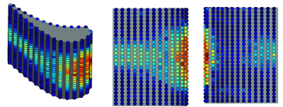
NASA and SCS have also shown temperature measurement capabilities for newly developed ceramic matrix composites (CMC) turbine blades in ultra-high temperature applications. These materials can experience loads between 1,300°C and 1,480°C, but new developments are under way to satisfy the needs for even higher firing temperatures. A thermal heating coating was applied, and more than 700 measurement points were taken to generate a temperature bubble plot.
Automotive turbochargers
Along with Bath University and Hieta in the UK, SCS conducted a validation study on additive-manufactured internally cooled turbocharger wheels using thermal history paint (THP). The THP was used to measure the temperature profile of the blade surfaces and the effectiveness of the cooling. The study resolved small-scale temperature gradients with a high number of measurement points not possible with traditional temperature measurement tools. Temperatures of up to 740°C were calibrated. The difference between the THP and thermocouple measurements was in most cases less than ±3K (0.4%) and all cases within 8K (1.2%). The standard deviation of repeat measurements on the samples was less than ±8.4K (1.2%). The values were also well within the expected uncertainty of the thermal simulation.